![]()
Andrej Karpathy has highly recommended Vibe Coding, which is becoming a favorite among developers. This experience of “just chatting, and AI can write the functionality” significantly enhances the efficiency of simple tasks.
However, when we turn our attention to actual systems, especially complex systems like AI Infrastructure, Vibe Coding often encounters the dilemma of being “out of place”.
Key Issues
In summary, there are three main issues:
- Context Loss: The dialogue history is compressed, and key design decisions are gradually forgotten during multi-turn interactions, leading to a disconnection between the generated code and earlier discussions.
- Decision Divergence: AI needs to make numerous technical decisions (such as architecture selection, interface design, error handling strategies, etc.) when facing complex systems. Autonomous decision-making can easily deviate from the developer’s intent, resulting in code that does not meet expectations.
- Quality Instability: Even with a complete requirement description, the quality of the generated code can vary greatly. The same requirement may yield entirely different implementation solutions at different times.
The root cause of these issues lies in the complexity of AI Infrastructure, which often involves tens of thousands of lines of code and hundreds of interrelated decision points. Current conversational programming lacks a persistent, structured decision management mechanism.
In other words, Vibe itself is vague and unstable, unable to support serious and complex infrastructure.
Nevertheless, the development of Vibe Coding is irreversible, and its potential for widespread application should not be halted. To make Vibe Coding truly applicable to AI Infrastructure development, we practiced a text-driven Vibe Coding method: by systematizing and persisting all key decisions through design documents.
By prioritizing key decisions of complex systems during the design phase and using structured documents, development becomes more orderly, significantly lowering the complexity threshold.
Programmers only need to focus on high-level design decisions, while AI handles the implementation details, achieving the goal of “completing complex functions with almost no code written”.
The entire process constrains AI generation through detailed design specifications and code logic, ensuring that the implementation meets expectations while enhancing system robustness.
To validate the effectiveness of this new paradigm, we need a typical scenario that combines high complexity, strong engineering constraints, and real business value.
The resource scheduling system in AI Infrastructure, especially for Agentic RL, is such an ideal testing ground. This system is a distributed training system with tens of thousands of lines of code, facing complex challenges in optimizing GPU utilization, involving core scheduling logic changes.
Part 1: GPU Utilization Challenges in Agentic RL
During the sampling process of Agentic RL, the system needs to support an increasing number of interaction rounds, allowing agents sufficient environmental interactions to handle complex tasks. However, this trend brings significant resource scheduling challenges.
In actual sampling, the time distribution of tasks executed by agents exhibits a typical long-tail characteristic: most samples can be quickly completed within a few rounds, while only a few complex samples need to execute to the maximum round limit to terminate. This uneven execution distribution becomes the core bottleneck for GPU resource utilization.
The essence of the problem lies in the classic “Straggler Effect” in distributed computing: regardless of how many samples have been completed, the system must wait for the slowest sample to finish before moving to the next stage. This waiting process becomes a performance bottleneck for the entire training flow, leading to GPU resource waste.
1.2 Solution Comparison and Technical Advantages
The industry has two mainstream solutions for Agentic RL training, both of which have fundamental flaws:
-
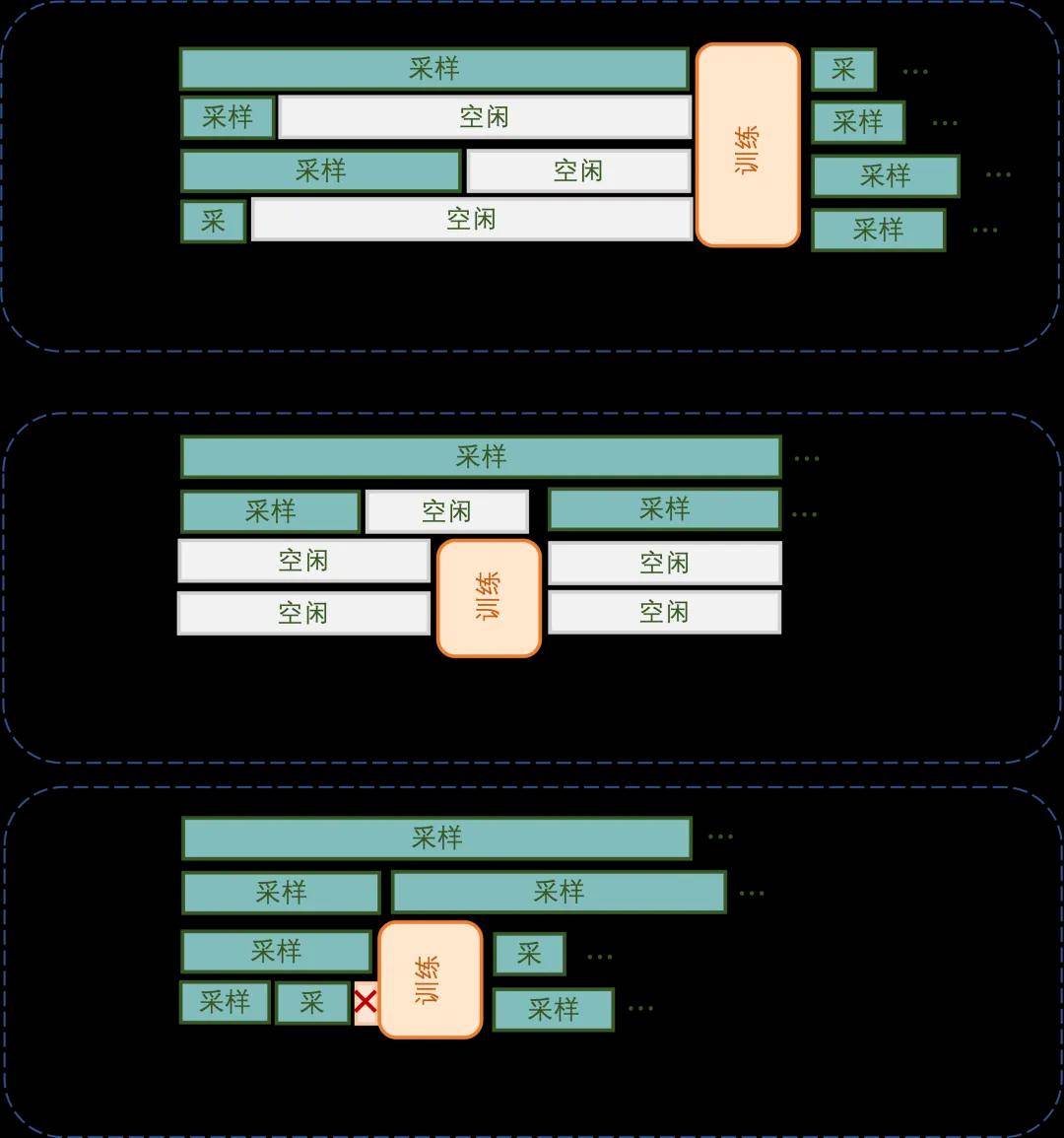
Co-location Solution: This adopts a strict serial execution strategy: all GPUs first uniformly enter the rollout phase and wait for all samples to complete before switching to training mode. This solution has dual efficiency issues. First, there is resource idleness during the rollout phase due to the Straggler Effect, where many GPUs enter idle waiting states after short samples complete. Second, the strict serial restriction between phases means rollout and training cannot be executed in parallel, significantly extending the overall iteration time.
-
Asynchronous Separation Solution: This achieves pipeline parallelism by statically allocating dedicated rollout GPUs and training GPUs. Although it theoretically shortens single-round iteration time, it introduces serious “double bubble” problems. On the rollout side, after short samples complete quickly, rollout GPUs enter idle states waiting for long-tail samples to finish; on the training side, after training tasks are completed, they must wait for new rollout data, leaving training GPUs idle as well. Thus, the theoretical parallel advantages are significantly diminished in actual operation.
We propose a time-division multiplexing solution that addresses the above issues through a dynamic allocation mechanism for GPU pools. The core innovation is based on a key insight: the demand for GPU resources during asynchronous training exhibits dynamic fluctuations. Before training is triggered, many samples have already entered the completion stage, resulting in a natural decrease in GPU resource demand. Conversely, after training ends, a large influx of samples into the system leads to a sharp increase in GPU resource demand, creating a clear peak period. Based on this fluctuation pattern, we designed an intelligent resource scheduling mechanism that allocates some GPU resources for training tasks during low-demand periods, effectively matching demand fluctuations with resource scheduling.
The system adopts a two-stage execution process to realize this design concept. During the full sampling phase, all GPUs collaboratively process most samples, quickly advancing the system to a low-demand state. When the sampling completion reaches training requirements, the system performs a scaling-down operation, releasing fixed rollout GPU resources for training mode. It then enters the parallel execution phase, where the released GPUs specifically execute training tasks (fully utilizing idle resources during the low-demand period), while long-tail samples are migrated to remaining GPUs for continued processing. After training tasks are completed, the system immediately performs a scaling-up operation, reclaiming all GPU resources to restore full sampling status, preparing for the next demand peak.
This intelligent time-division multiplexing strategy, based on workload characteristics, is not merely resource segmentation but cleverly matches the rapid execution characteristics of training with the demand fluctuations of rollout in the time dimension, enhancing overall GPU resource utilization efficiency.
Using a 4 GPU system as an example, we compare the task execution timelines of each solution.
The core challenge of the time-division multiplexing solution lies in the significant increase in system complexity. To pursue high performance, a finely-tuned control mechanism is required, which is particularly difficult to implement in a distributed high-concurrency system. Compared to serial execution and static resource allocation, dynamic scheduling introduces numerous technical difficulties: precise synchronization control in a distributed environment and atomic guarantees for scaling operations, as well as seamless migration of sample states in concurrent scenarios.
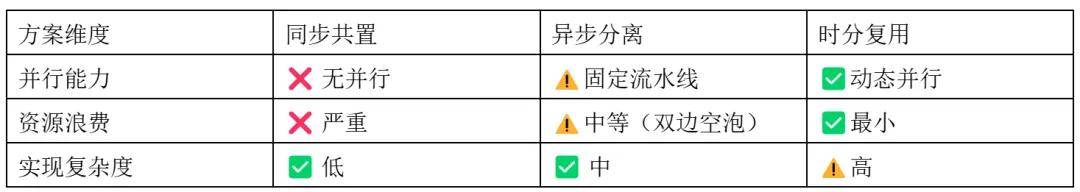
Advantages and Disadvantages of Each Solution
In a distributed RL system containing tens of thousands of lines of code, manual coding not only takes a long time but also easily introduces hidden state inconsistency bugs. Traditional development methods have struggled to meet the demands of such “high-value, high-complexity” feature iterations.
It is against this backdrop that we innovatively adopted a document-driven Vibe Coding methodology, significantly enhancing the implementation efficiency and code quality of complex systems through systematic design documents.
Part 2: Document-Driven Vibe Coding Methodology
The three major pain points of Vibe Coding mentioned earlier—context loss, decision divergence, and quality instability—are all rooted in the same issue: the lack of persistent, structured decision management mechanisms.
To understand how design documents address this issue, we first need to recognize the essence of code implementation: it consists of hundreds or thousands of interrelated decision points. From top-level architecture choices and interface designs to bottom-level variable naming and error handling, each decision impacts the final code quality. Ideally, if AI has mastered the complete code changes (such as a code migration task), it can directly replicate these modifications. However, in reality, the problems we often need to solve are entirely new, such as the “training-inference time-division multiplexing optimization” feature discussed in this article, which has never been implemented before.
Since there is no existing code to reference, we can at least systematically enumerate all decision points, allowing AI to generate code step by step according to these clear decisions.
Design documents are the key tool to achieve this goal: they systematically refine high-level design ideas into specific code changes, fully documenting each decision point.
A design document reviewed by programmers means that humans and AI have reached consensus on key decisions. This directly addresses the three major pain points of Vibe Coding: persistent documents eliminate context loss, clear decisions prevent AI from diverging from intent, and specifications and code logic ensure stable code quality. This brings about a fundamental shift in work methods: programmers move from coding, debugging, and testing to discussing design with AI, clarifying decision points until fully aligned, and then AI is responsible for implementation. Design documents also record implementation progress, ensuring traceability. More importantly, design documents are managed by AI, significantly lowering the barrier for writing.
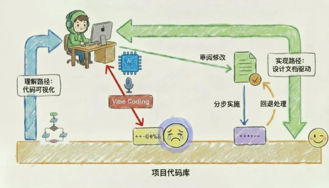
Comparison of Document-Driven Vibe Coding and Traditional Vibe Coding Workflows
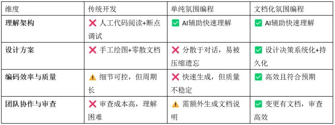
Advantages and Disadvantages of These Three Development Methods
2.1 Core Methodology: Design Document-Driven Development
Once the necessity of design documents is clarified, we need to establish a systematic methodology to guide practical operations. Document-driven development is not just about writing documents; it is a completely new development paradigm: organizing the decision process through structured documents, ensuring decision quality through iterative reviews, and reducing implementation risks through step-by-step execution.
The core of this methodology lies in breaking down complex system development issues into three manageable segments: content organization (how to construct the decision system), review and modification (how to ensure decision quality), and step-by-step implementation (how to translate decisions into code). Each segment has clear operational processes and quality standards, ensuring the controllability and predictability of the entire development process.
2.1.1 Process Overview
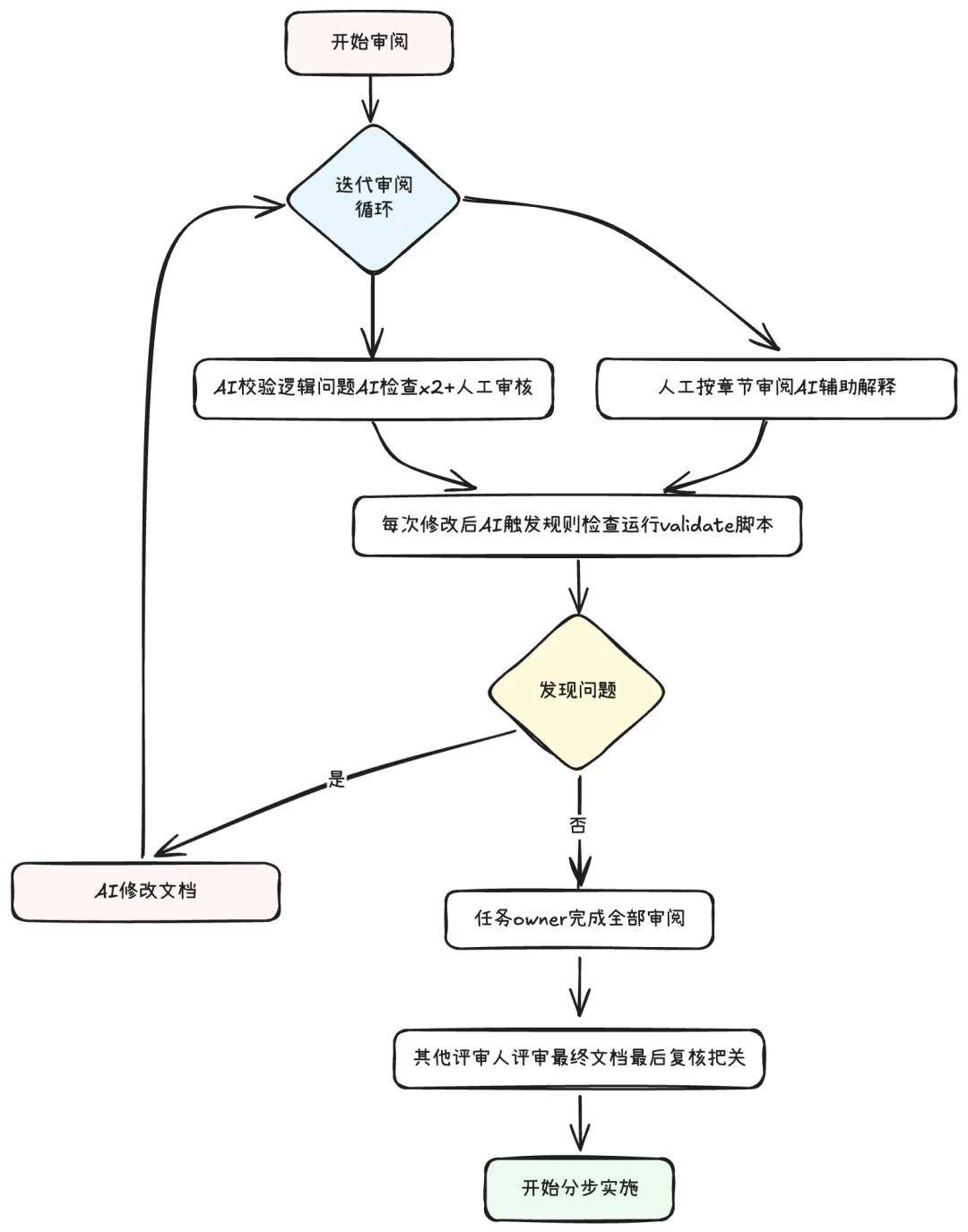
The review of design documents is an iterative optimization process that requires collaboration between humans and AI to ensure document quality. We established a systematic review process, gradually refining the design documents through multiple iterations until they meet implementation standards.
Overall Review Process
2.1.2 How to Organize Content: Collaboration Between Developers and AI
The results of code implementation are determined by a series of top-down decisions. Key top-level decisions include how new features integrate into existing architectures, while bottom-level decisions involve whether to add member variables. The core purpose of organizing design documents is to systematically follow these decision points and gradually refine solutions. Since bottom-level decisions often depend on top-level or higher-level decisions, design documents need to hierarchically break down decisions to form a decision system. Developers need to review the top-down decision process in the document according to the order of chapters and the hierarchy of the table of contents. When we point out errors in earlier top-level designs, AI will automatically modify the mid-level and lower-level decisions in subsequent chapters to maintain internal logical consistency. Thus, we can align top-down decisions with AI chapter by chapter. Meanwhile, the document evolves as developers and AI jointly correct these decisions, and the document needs to be self-contained to record this iterative process, including the iteration versions. Finally, the document must also record the progress of code implementation and any derived to-do items.
Specifically, our design document template includes the following content:
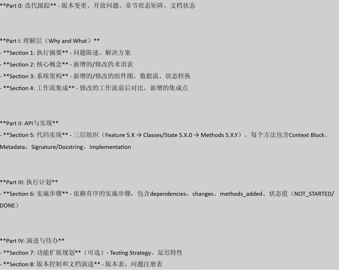
2.1.3 How to Review and Modify: Reusing iFlow CLI’s Prompt Templates
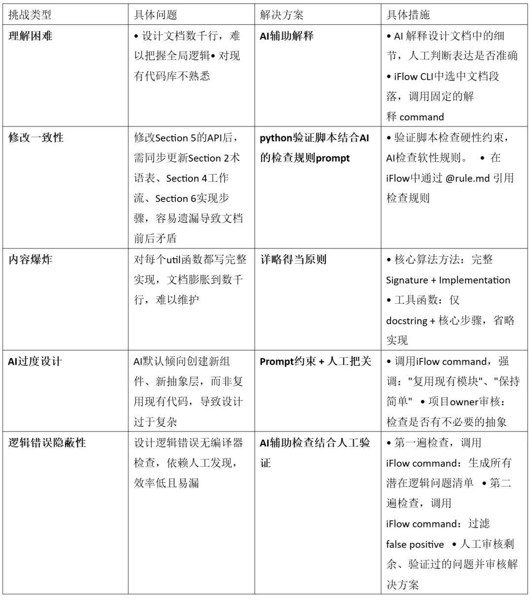
The chapter-by-chapter review alignment process described above is theoretically complete, but practical challenges arise. To address these challenges, we established a multi-layered document quality assurance mechanism.
Since these scenarios repeatedly occur in document reviews, we utilized the Sub Command feature of iFlow CLI to solidify the logical instructions of different scenarios into custom prompt templates.
Review Challenges and Corresponding Solutions
2.2 Implementation of Design Documents
2.2.1 How to Plan and Implement in Steps
Once Section 5 has completed the design of all APIs and implementations, we need to translate these designs into executable code. This translation process is divided into two phases: first, planning Section 6 to establish implementation steps, and then entering an AI-assisted incremental development loop.
Planning Implementation Steps: The core goal of planning is to break down the methods in Section 5 into dependency-ordered small steps. We first analyze the deps: field of each method to identify the dependencies between bottom-level helper methods and top-level orchestration methods, drawing a complete dependency graph. When breaking down steps, we follow the principle of “the smaller the step, the better”; typically, a step contains 3-5 interrelated methods, avoiding a single step containing more than 10 methods. The order of steps follows dependency relationships: Step 1 usually involves infrastructure (configuration, constants, base classes), and Steps 2 to N are arranged in order from bottom to top, with the last step responsible for integration and end-to-end testing. Each step defines clear validation points and test case coverage, ensuring independent verification and ease of rollback.
After planning, we obtain a clear dependency graph to guide subsequent incremental development:
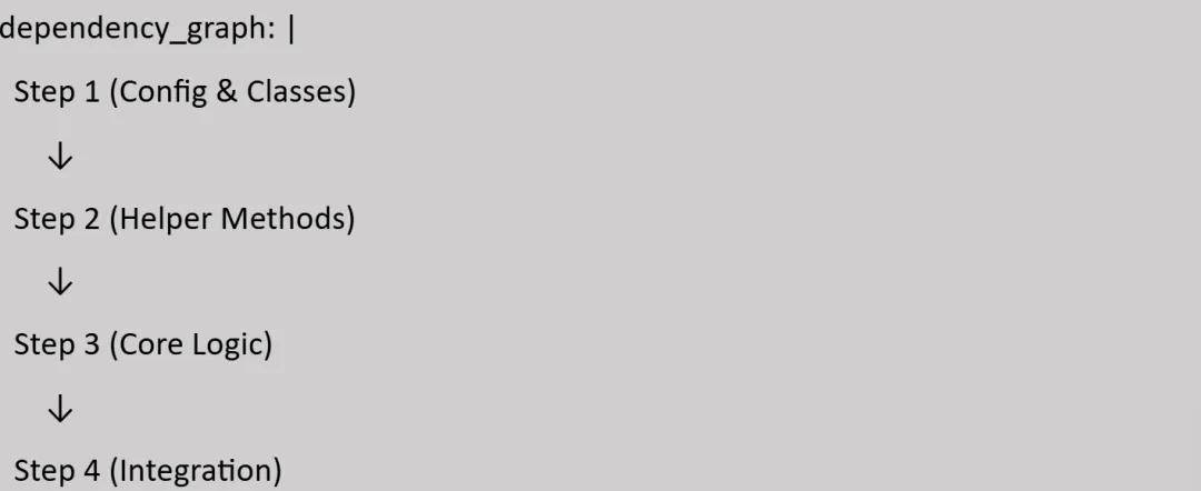
Incremental Development Loop: After planning Section 6, we enter the implementation phase. For each step, AI first reads the purpose and dependencies in Section 6, along with the signatures and implementations of related methods in Section 5, then generates specific code according to the docstring and code implementation, while expanding validation placeholders into actual validation logic. Once AI completes coding, it automatically updates the status of that step in Section 6 from NOT_STARTED to DONE.
Next is the manual code review phase. We use the Local History feature of the IDE to view code changes for the current step, focusing on whether the code aligns with the design in Section 5, whether it correctly implements validation and assertions, and whether there are obvious bugs. If issues are found, minor corrections are made, or we enter the error handling process (see 2.2.3). After passing the review, we create a git commit, with the commit message following the format “Step N: [description]”, then proceed to the next step, repeating this loop until all steps are completed.
2.2.2 Defensive Programming: Making Complex Systems More Reliable
In a distributed AI training environment, small errors can trigger cascading failures, and the complexity of asynchronous operations and resource scheduling makes problem tracing inherently difficult. Worse still, AI programming tends to proactively handle errors, and this “goodwill” handling mechanism often backfires, obscuring real error information and complicating problem localization. What we truly need is defensive programming that exposes errors rather than concealing them. However, traditional defensive programming is often selectively ignored by developers due to its cumbersome nature and progress pressure, leading to system robustness relying entirely on individual conscientiousness. Therefore, we preemptively incorporate defensive thinking into the design phase: setting validation points at critical nodes, constructing a standardized error handling pattern library, and utilizing AI technology to automatically generate robust defensive code, thus achieving rapid problem localization while ensuring development efficiency and significantly reducing maintenance costs.
Unified Validation Pattern Library: We maintain a library of commonly used validation patterns, each with a unique ID and standardized implementation. These patterns follow the principle of single definition and multiple reuse. When needing to add a validation logic in the code, developers only need to include a definition from the pattern library in comments, and AI will expand it according to the ID during implementation, ensuring consistency of the same validation logic throughout the codebase.
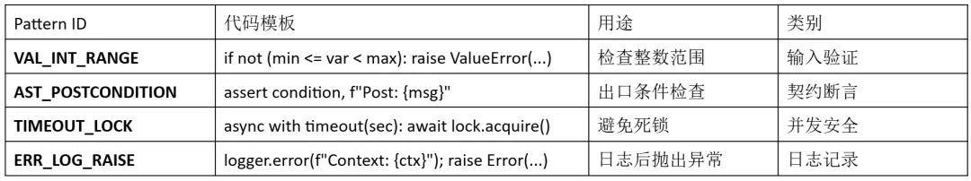
Validation Annotations in the Design Phase: In the design document of Section 5, we do not directly write complete validation code but use standardized comments to annotate validation requirements. For example, in the shrinksampler() function, we annotate the legality validation of the GPU list with VALINTRANGE and the validity check of the return result with ASTPOSTCONDITION. This annotation method clearly expresses the validation intent while maintaining the simplicity of the design document.
def shrink_sampler(self, target_gpus: List[int]):
    # VAL: VAL_INT_RANGE (min=0, max=7)
    # Will be expanded into actual validation code during implementation
    offload_ranks = self._calculate_offload_ranks(target_gpus)
    # AST: AST_POSTCONDITION (len(offload_ranks) > 0)
    # Will be expanded into assert statements during implementation
    return offload_ranks
AI Automatically Expanding Validation Logic: When AI generates code based on the design document, it will automatically expand the pattern IDs in the annotations into specific validation logic. Parameter range validation will be expanded into complete condition check statements, and post-conditions will generate assert statements with detailed error information. This automatic expansion mechanism avoids omissions and inconsistencies during manual coding.
# Annotations in the design document:
# AST: AST_POSTCONDITION (len(offload_ranks) > 0)
# AI expands into an assert statement with detailed information during implementation:
assert len(offload_ranks) > 0, \
    f"Post-condition: offload_ranks not empty, got {offload_ranks}"
Independent Handling of Complex Validations: When validation logic exceeds 10 lines, inline expansion can make the code cumbersome and hard to read. For such complex validations, we define dedicated validation functions in the design document, detailing the validation items and error handling strategies. For example, the validategpuallocation() function is responsible for validating the integrity of GPU allocation logic, including checking that target_gpus is non-empty and ensuring GPU IDs are within valid ranges. In the implementation plan, we arrange dedicated steps to implement these complex validation functions, providing a solid foundation for subsequent core logic steps.
#### 5.2.8 _validate_gpu_allocation() - Full Specification
def _validate_gpu_allocation(self, target_gpus, current_allocation):
    """ Validate the complex logic of GPU allocation.
    Checks:
    - target_gpus is non-empty and elements are unique
    - GPU IDs are within valid ranges
    Raises:
        ValueError: Violates any check condition
    """
    # 10-20 lines of detailed validation logic
Part 3: Validation on Production-Level Large-Scale Clusters
3.1 Experimental Configuration
We validated the actual effects of the time-division multiplexing solution on a production-level large-scale cluster. The experimental environment used a 160-card GPU cluster and selected a representative SWE Agentic workload as the test scenario. The model used was Qwen3-235B-A22B, a large-scale language model with 235 billion parameters and 22 billion activation parameters, capable of fully reflecting the computational pressure of a real production environment.
To simulate a real agent long-term interaction scenario, we set the maximum interaction rounds to 100, the maximum token length to 64K, and the batch size to 512. We set the async ratio of asynchronous training to 1, ensuring the authenticity and challenge of the experiment. In the comparison scheme setup, we compared the time-division multiplexing solution with the traditional asynchronous separation solution: the baseline used a static allocation strategy of 128 cards for training and 32 cards for rollout, while the time-division multiplexing solution used 128 cards for training and 160 cards for rollout with dynamic scheduling.
3.2 Performance Comparison Analysis
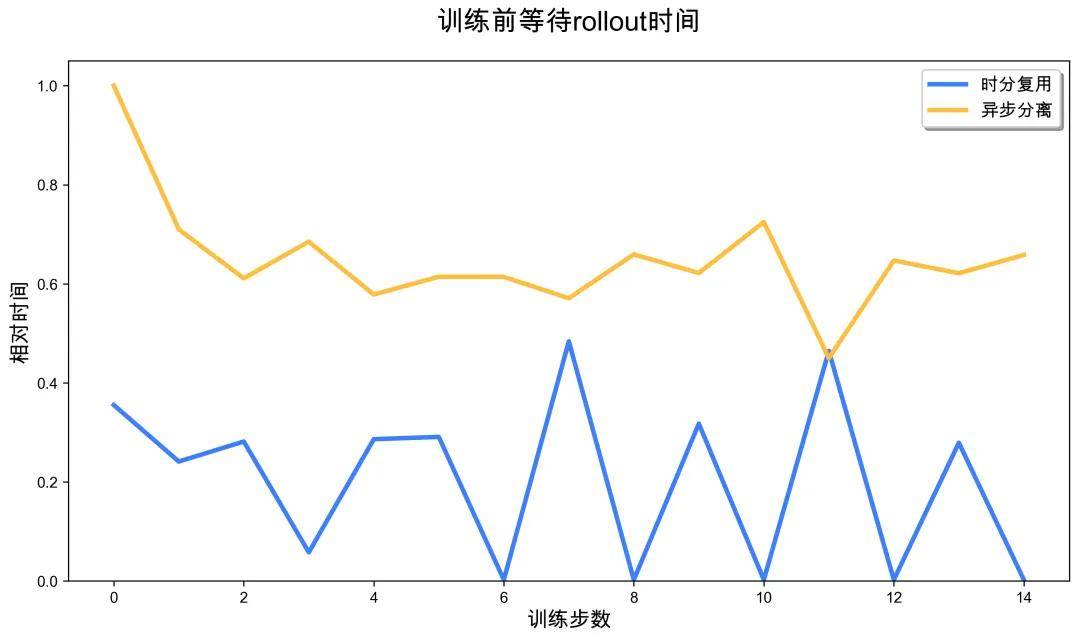
The experimental results showed that the rollout throughput of the time-division multiplexing solution increased by 3.5 times. The rollout phase of the time-division multiplexing solution was almost always faster than the completely separated baseline, and in some cases, training tasks could start without waiting for rollout, showing significant performance improvements.
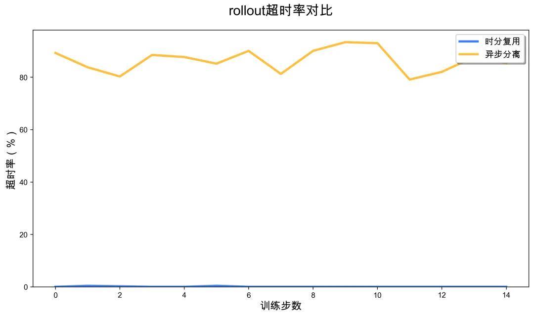
More notably, the task completion rate improved. In the baseline’s completely separated solution, due to limited rollout resources (only 32 cards), the sampling speed was slow, causing many tasks to trigger the environment’s default timeout limit, leading to a high timeout ratio in sampling trajectories. In contrast, the time-division multiplexing solution dynamically released more GPU resources for rollout, significantly accelerating sampling speed, completely avoiding timeouts, and enhancing overall training stability and sample utilization efficiency.
3.3 System Overhead Analysis
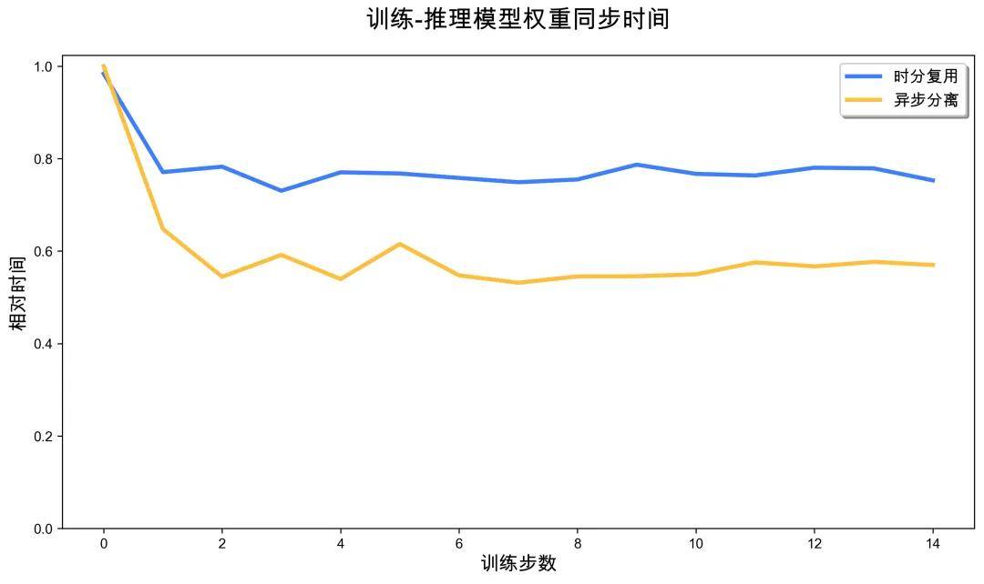
When evaluating the time-division multiplexing solution, we also carefully analyzed the system overhead introduced. Regarding parameter synchronization overhead, since the time-division multiplexing solution requires parameter synchronization across more GPUs (160 cards vs. 32 cards), it incurs additional communication overhead compared to the separation solution, but this overhead accounts for a very small proportion of the overall training time.
The overhead from scaling-down operations mainly comes from the offload process of rollout model parameters. When the system needs to switch some GPUs from rollout mode to training mode, it must release rollout parameters from the VRAM, which takes seconds in practice. Although this operation introduces an additional synchronization point, its overhead is very low and does not become a performance bottleneck.
Overall, the time-division multiplexing solution significantly enhances GPU utilization and training efficiency while introducing minimal system overhead, particularly excelling in reducing timeout rates, fully demonstrating its practical value in large-scale Agentic RL training.
Part 4: Team Introduction
This article is the exploration result of the ROCK & ROLL team using iFlow CLI in open-source framework practice, and related functions will continue to iterate and be released.
ROCK & ROLL is a joint effort between Alibaba’s Future Life Lab and the Intelligent Engine team, dedicated to pioneering the future of reinforcement learning (RL) and exploring innovative lifestyles for the future. ROLL is a flexible and efficient Agentic RL training framework that supports optimization training from billion to hundred billion parameter large models; ROCK is an easy-to-use, scalable sandbox environment manager that can launch massive environments in minutes. We adhere to the collaborative innovation of engineering systems and algorithms, continuously focus on the development of the RL community, and share open-source practices to provide solid infrastructure support for the large-scale implementation of RL in various scenarios.
iFlow CLI is a terminal AI agent launched by Alibaba’s Future Life Lab, supporting interaction through natural language. It can efficiently analyze code repositories, complete various programming tasks, and accurately understand specific contextual requirements; it can also automate processes from basic file operations to complex workflows, significantly enhancing developer productivity.
We welcome you to follow, star, try out, and contribute code to jointly promote RL for LLM towards a broader practical future.
- ROCK: https://github.com/alibaba/ROCK
- ROLL: http://github.com/alibaba/ROLL
- iFlow CLI: https://cli.iflow.cn/
Comments
Discussion is powered by Giscus (GitHub Discussions). Add
repo,repoID,category, andcategoryIDunder[params.comments.giscus]inhugo.tomlusing the values from the Giscus setup tool.